Building a quadcopter with vision-based obstacle avoidance

Intelligent and electric vehicles are coming that can fly better and safer than anything ever built.
Distributed electric propulsion (DEP) redefines safety and simplicity for aerial mobility. DEP involves using multiple electric motors distributed across the vehicle, enhancing safety through redundancy. This also enables vertical takeoff and landing (VTOL) capabilities similar to helicopters, without autorotation but with said redundancy.
DEP also offloads most of the compute required for human piloting, making flying almost trivial for autopilot multicopters and VTOLs. No human could adjust the speed of multiple electric motors hundreds of times per second or more. Only software could do that. Control systems including PID controllers, maintaining altitude and spatial positioning with GPS, stabilizing orientation and pitch/roll/yaw all happen on flight controllers with less than 500 MHz clock speeds (and some less than 200 MHz). That’s a processor with merely late 90s to early 2000s Intel x86 CPU speeds!

Directing my quadcopter to lift off the ground and hover for the first time was wild. It was an aha moment of how stable and safe (and cheap) the consumer tech is today, and where it is headed.
Flying a well tuned multicopter is *far* easier than driving and as easy as playing a video game. The difficulty is the hardest it will ever be.
But we will not need to do much flying ourselves at all. Autonomous capabilities of multicopters are already incredibly impressive with relatively cheap hardware and a 200 line python script (more later). They can detect obstacles using vision and/or LIDAR, and unlike terrestrial EVs, do not have to contend with road rage, cyclists and busy parking lots. The best way to avoid obstacles is if there are no obstacles, much easier done at 1500ft/500m above traffic than in traffic.
Of course, I’ve not even mentioned other important enablers. Ever improving battery technology, increasing specific power of electric motors and inverters, better power electronics, composite materials and the rise of consumer robots are rapidly expanding the design space for drones and flying EVs.
I don’t think enough people have truly grasped how game changing this all could be. I’m not sure it’s possible to without getting your hands on current generation HW and SW, and seeing the potential firsthand.
As I continue tinkering more in this space, I’ll write more about the tech stack and share more about I see things going. Briefly: not air taxis you can’t own. Instead, a flying EV you own and can land in your own (initially large) yard that is very safe and easy to fly, with surprising range and enough payload for two.
Ok, let’s get into my quadcopter build.
Why build a quadcopter
I wanted to assemble my own quadcopter to see if I would enjoy it and gain intuition quickly on the build process and flying. Both were a resounding yes, and motivated me to continue tinkering.

I was blown away at what quadcopters were capable of. High level learnings:
So easy to fly and incredibly stable GPS-assisted hover
Planning missions is easy to use and setup
With some work and help from GPT, impressive autonomous obstacle avoidance
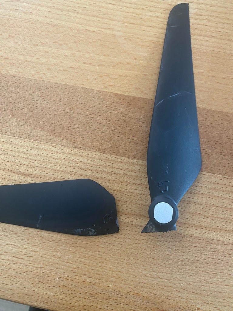
Components are rock solid. Except for props, unsurprisingly. They break. A lot
Contents
Build requirements
Multicopter. I wanted similar flight characteristics to an eVTOL (electric VTOL) in hover. A quadcopter was the simplest rotor configuration.
Weight and size. Bounded by cost and space in my workshop aka living room at the time. Chose a 20 inch (50 cm) quadcopter frame with 10 inch propellers (props) and good payload.
Build speed and instructions. Found a quadcopter that I estimated I could assemble in an hour or so as a newbie.
Ease of flight and controls. I wanted the easiest possible controls with software taking as much cognitive load as possible. That meant an autopilot drone, not one for FPV racing. A reason for this is that personal eVTOLs should be as simple to fly as using an iPhone.
Ease and speed of part replacement. Likely that I would crash many times (and I did ofc), and I needed to be able to order parts for repairs as quickly as possible.
Autonomous capabilities. I wanted to test obstacle avoidance and autonomous flight features — ideally both vision and lidar based systems and onboard compute for vision.
Hardware and software
There were only two firmware/software options that made sense for an autopilot drone. These being PX4 and Ardupilot, both open source.
I chose PX4 for my quadcopter build initially because it was easier and faster to get started with. PX4 is maintained by the non-profit Dronecode Foundation, a part of the Linux Foundation. I later switched to Ardupilot for the quad (and my first radio controlled VTOL build) because of better support for autonomy features. QGroundControl, the recommended ground station software for PX4, had a Mac app and seemed easy to start with. I wanted to avoid needing to set up a Windows environment if possible, but it was not in the end.
Frame and dev kit
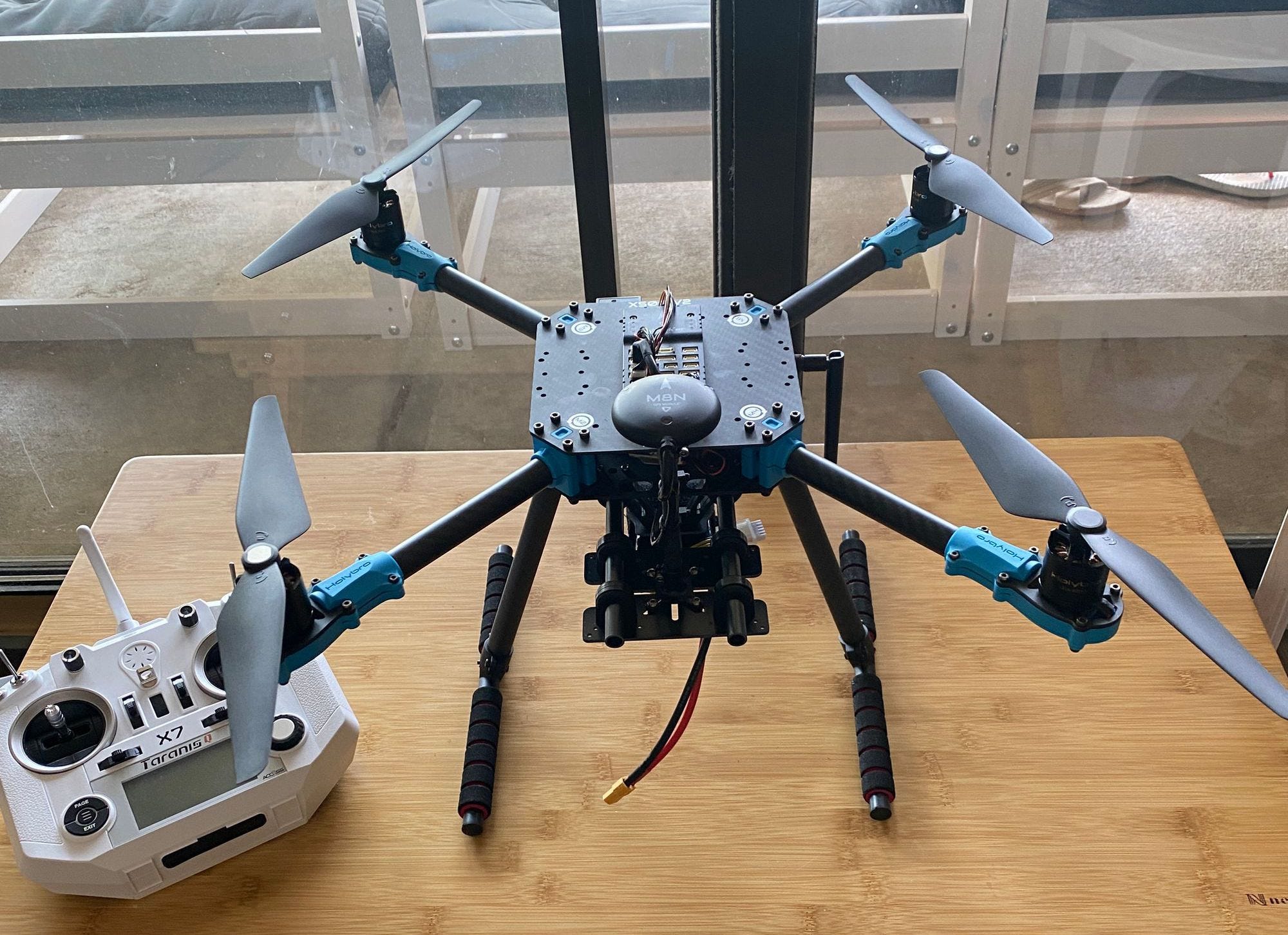
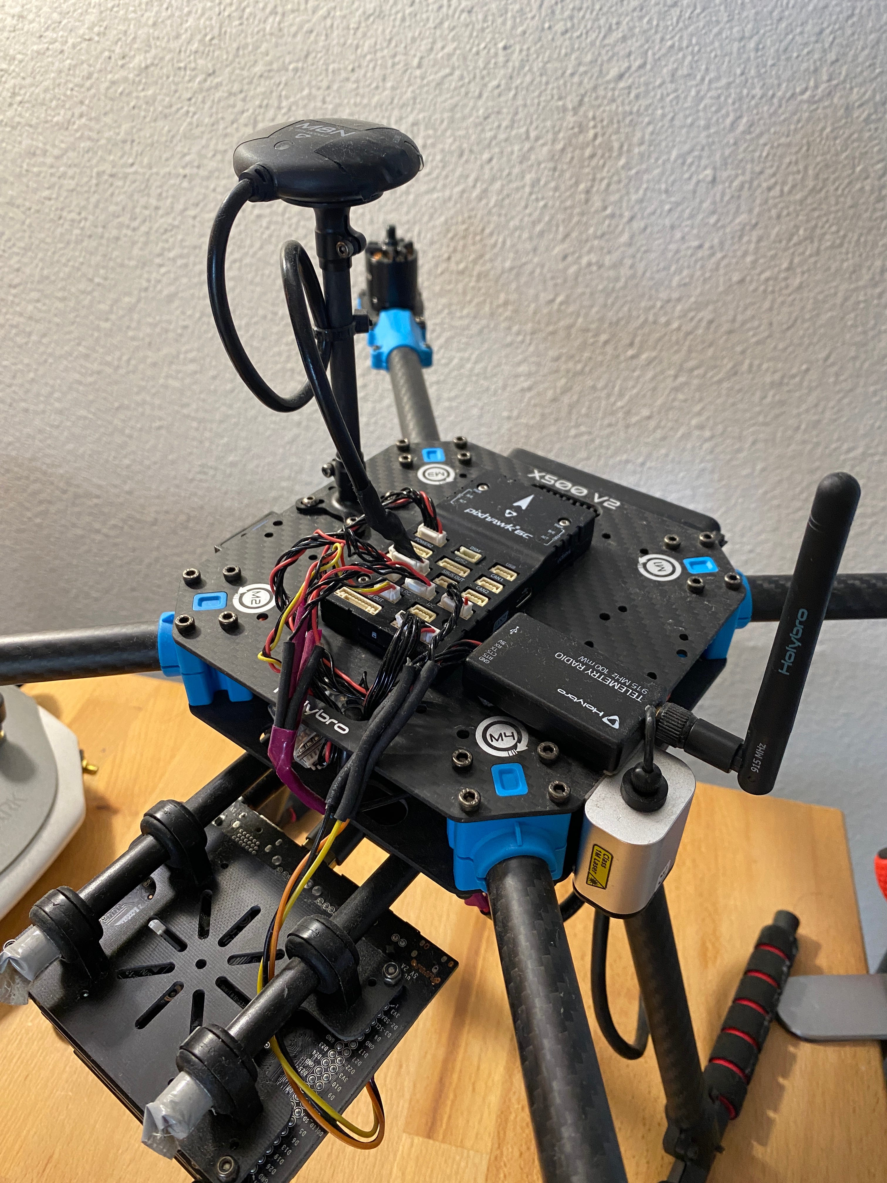
As for the hardware, first I chose the X500 v2 dev kit from Holybro. Affordable, fast and easy assembly for my first build, good payload, with space for a companion computer for running computer vision algorithms.
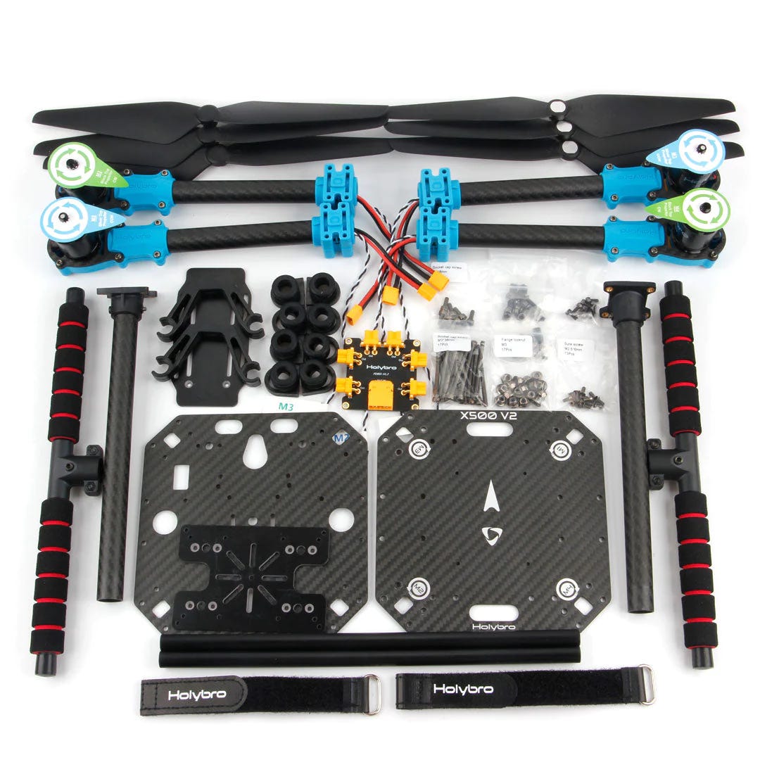
Some specs:
No soldering required (again for speed)
510mm (20 inch) frame size
carbon fiber CFRP frame with fiber-reinforced nylon connectors
610g (1.34 pounds) empty weight
1500g (3.31 pounds) payload including battery
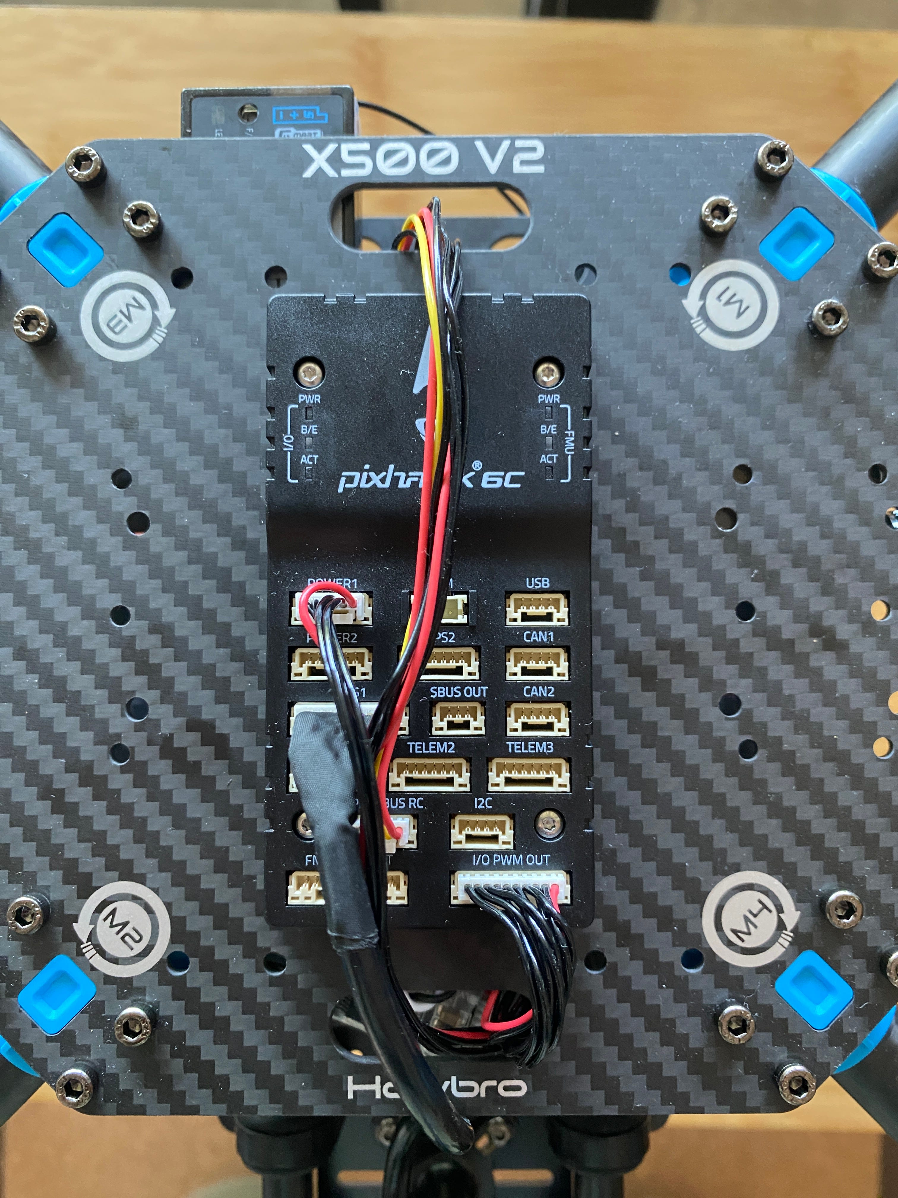
35g Pixhawk 6C flight controller with 480 MHz Arm processor, 1 MB SRAM and onboard IMU with accelerometer, gyro, magnetometer and barometer
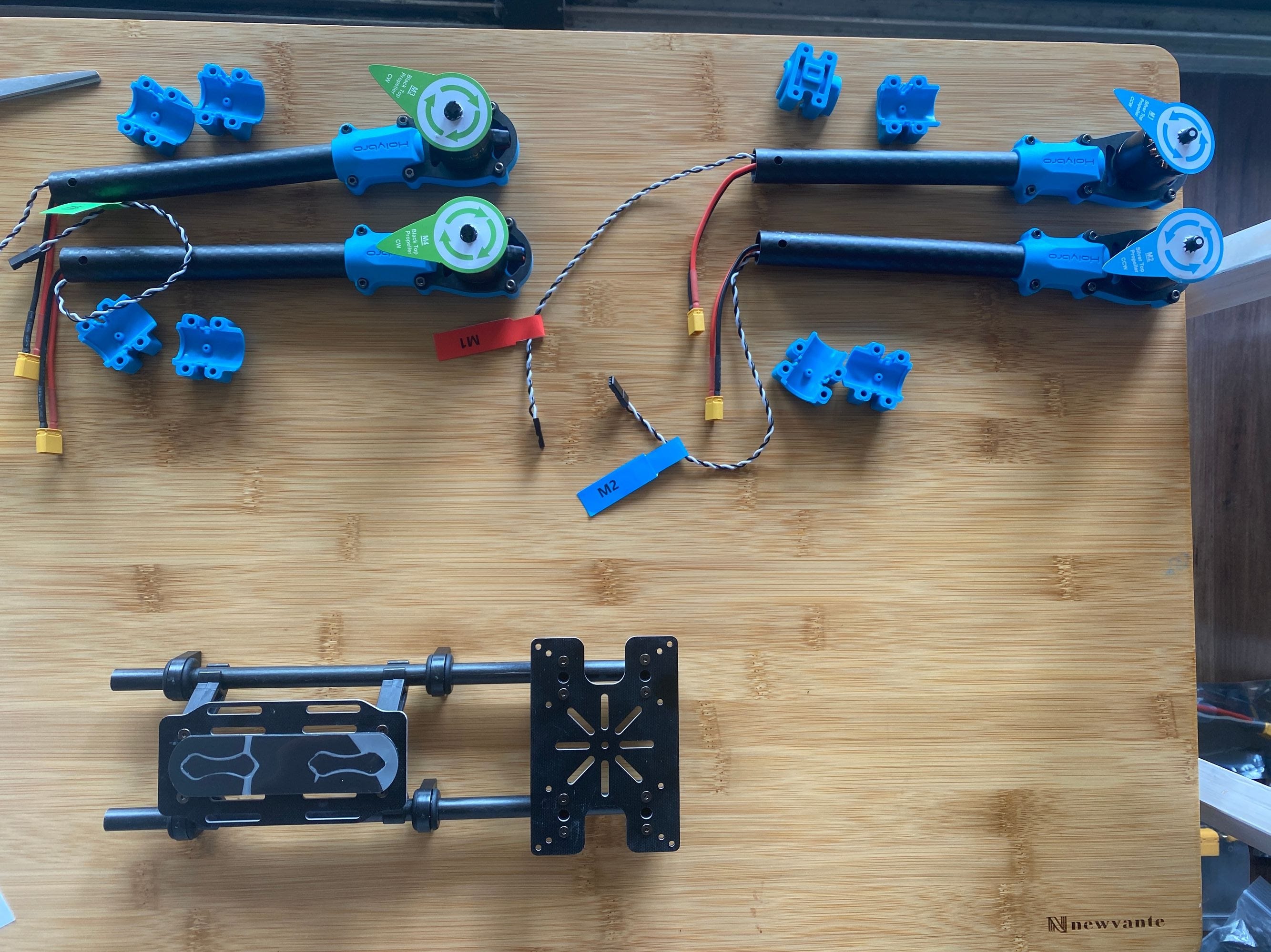
4x 920KV 272W (17A @16V) motors
4x 20A continuous current electronic speed controllers (ESC)
4x 10 inch propellers with two spares
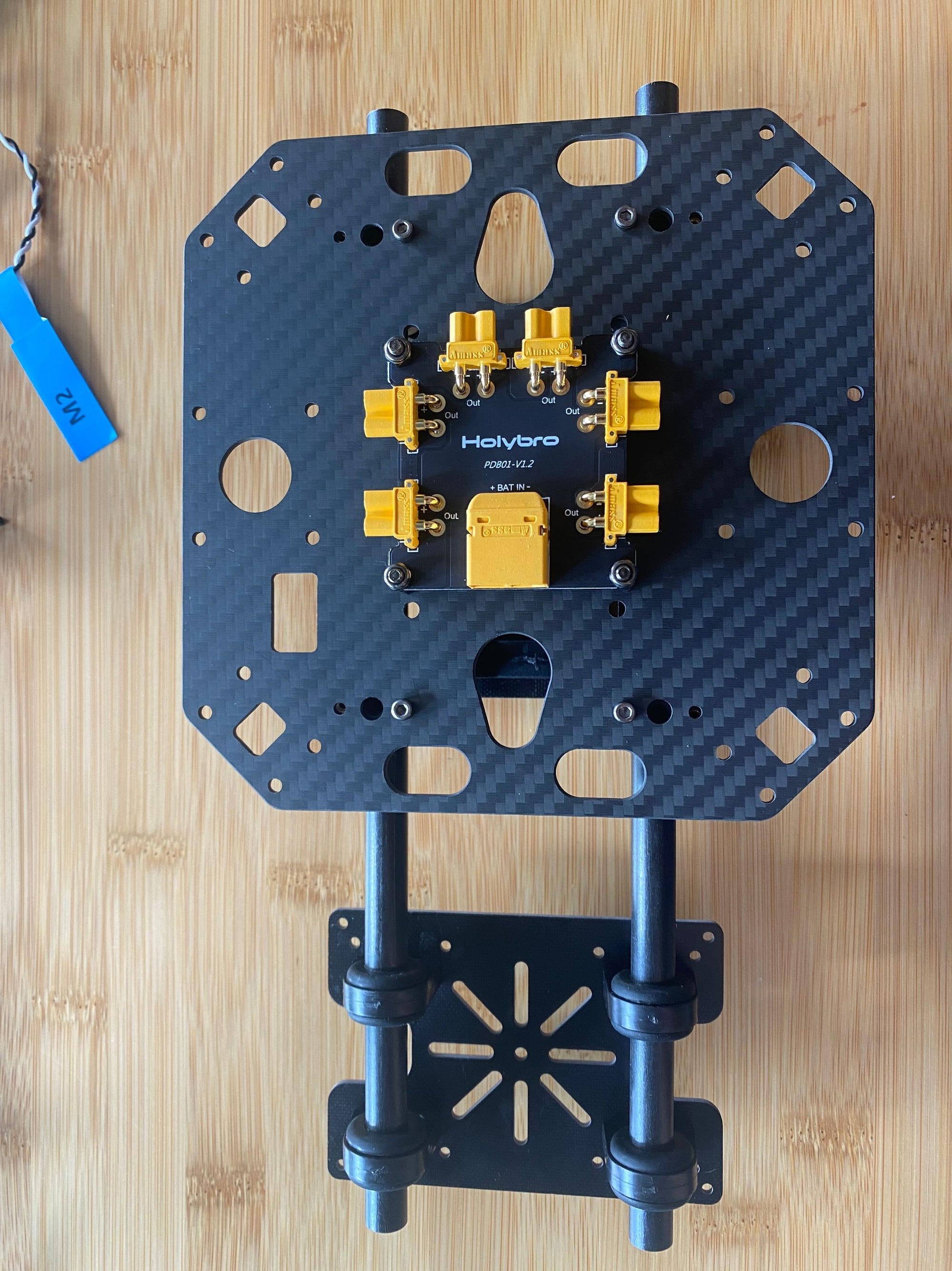
Power distribution board with XT60/30 connectors
32g/1.1oz GPS module included (up to 32 simultaneous satellites) with built in compass
Telemetry radio (for sending live telemetry data to ground station app on my Mac)
All for $575, ordered from US based multicopter retailer NewBee with a 30 day warranty.
US sourced components?
Sourcing these components from the US would have been ideal, but there was not anything close to the price point that I could find. Modal AI, a Qualcomm spinout, offered this 24 inch dev kit for $3700 though it does include significant onboard compute. They target use by US government agencies with Blue UAS 2.0 certification. Driving down the cost of US drone components is another topic, but Andrew Bunnie Huang’s post is a good place to start.
The same day I posted this, Alex Klimaj from Ark Electronics actually launched a pretty impressive US made flight controller for $165. It features similarly spec’ed and speed controller to the Pixhawk 6C, and is comparable in retail pricing. Some caveats are that the Ark FC is single PCB, made more for FPVs, and is between 1.5 to 2.5x more expensive than other single board FPV FCs from China. Still, it’s promising progress!
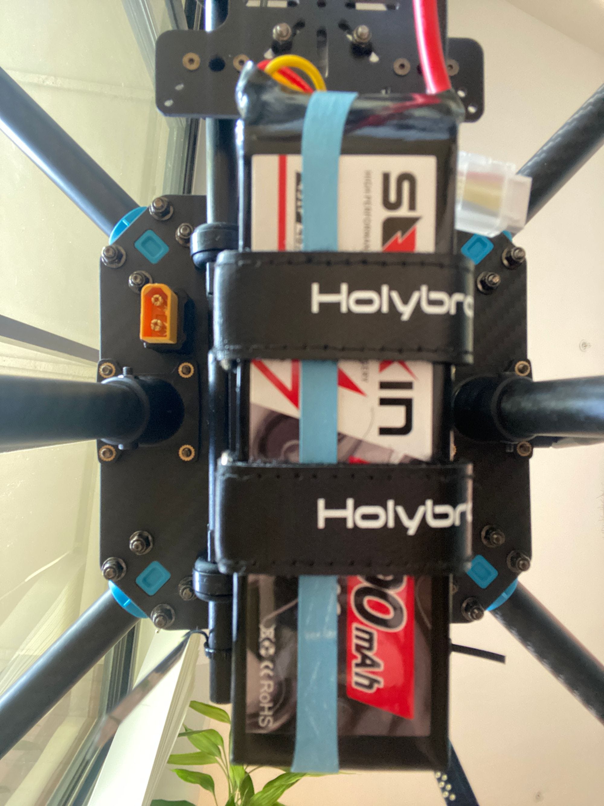
Battery
The frame came with recommended specs for a battery and I went with this lithium polymer 4S 3300 mAh 80C pack for only $35. Let’s break down what that means.
Lithium polymer (LiPo) batteries have a polymer electrolyte, instead of a liquid one found in standard lithium ion batteries (LIBs). LiPo packs have more specific power (power per unit mass) than LIBs, and are usually used for FPV racing quads, as well as autopilot quads. Specific power is expressed as a higher C discharge rating. An 80C pack means the battery can discharge at 80x current of the rated mAh (or Wh) capacity, in this case at 264 amps or 3.9kW! That’s enough power to (briefly) run a central heat pump HVAC or an EV cruising at 30 mph (48 kph) for less than a minute.
4S means there are 4 3.7V cells wired in series, increasing the voltage of the cells without increasing the current. This allows it to more efficiently run the brushless DC motors and ESCs with less heat loss. More EVs and eVTOLs now run an 800V architecture would require about 216 3.7V cells in series, and enough cells in parallel to meet the current draw for these vehicles.
To charge my LiPo, I sourced this ISDT charger capable of both AC and DC input for $65. It can balance charge LiPo cells at 200W with DC input, but the 50W AC input was plenty for recharging my LiPo at its recommended 1C charging speed. It can also discharge the LiPo cells to ~3.75 V, essential for safe storage when not in use.
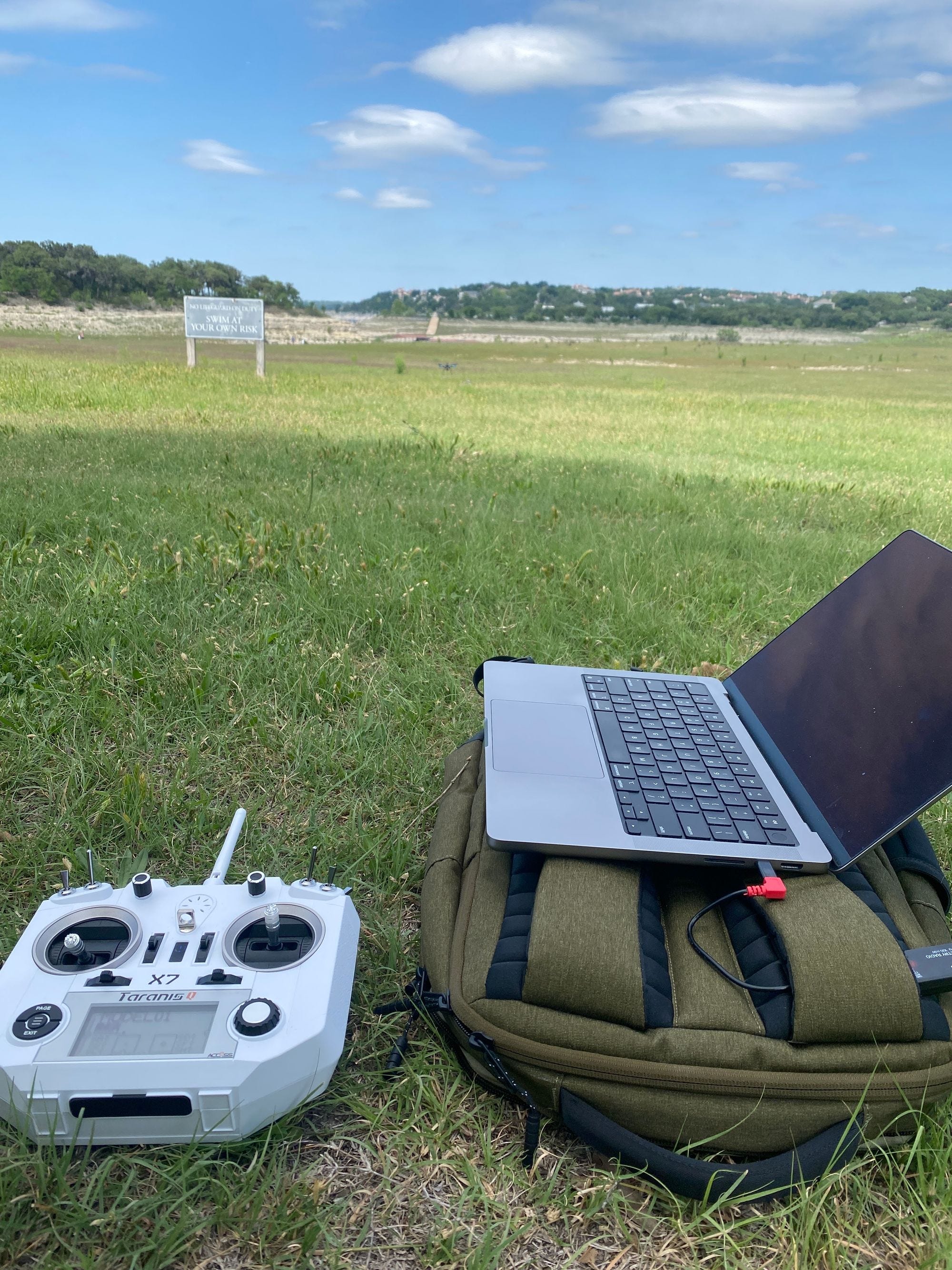
Radio controller
I chose to pair the Frsky Taranis QX7 transmitter (Tx) with the Frsky Taranis X8R receiver (Rx), which allowed a solder-free connection to the flight controller. The Tx and Rx cost me $178.

That brings the total cost to less than $800 (sans battery charger). I just had to assemble it and then maiden, aka do a maiden flight.
Assembly
Assembly was fast and I’m glad I picked this beginner friendly dev kit. The process helped me gain a much better intuition for quadcopters including integration of components, distributed electric propulsion and the high strength/weight for carbon fiber parts.
For reference, I used this and this video guide, as well as the build guide in the PX4 docs and took less than an hour for the dev kit. There was more time needed for pairing the Tx and Rx and setting up qGroundControl.
Once assembled, I next had to pair my radio Rx and Tx and finally calibrate sensors and configure parameters in the qGroundControl app.
With the hardware assembled and software set up, I was ready to maiden!
Maiden
Smooth as butter. That sums up how the maiden flight went. As a first time flier, I was surprised just how stable the quad was in hover.
How a multicopter hovers
This comes down to the PX4 software doing all of the heavy lifting to maintain level flight. PX4 and other autopilot software like Ardupilot have very mature control system architectures.
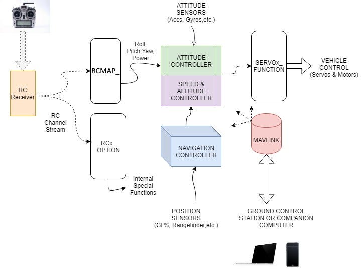
Sensors on the flight controller like the accelerometer, gyroscope, altimeter, etc all input data streams to the attitude controller, which maintains orientation in space.
Position sensors like GPS and rangefinders (more on this later) help keep the quad stable in the horizontal plane and altitude. The GPS input corrects for drift from wind, and helps the altimeter estimate altitude.
Inputs from my RC transmitter are mapped to pitch, yaw, roll and climb/descend controls for the attitude controller. The image below shows how these map to position flight mode, the mode in the autopilot software that maintains altitude and positioning if you don’t move the joysticks on your transmitter.
The attitude (and speed and attitude) controllers then sends the inputs to the ESCs (electronic speed controllers, also known as inverters) which provides millisecond-speed, 3 phase AC to power the electric motors. This AC current allows the thrust output for every motor to be precisely and rapidly controlled. For example, to pitch and move forward, the flight controller increases thrust to the rear motors, while making smaller adjustments to compensate for altitude, wind, etc.
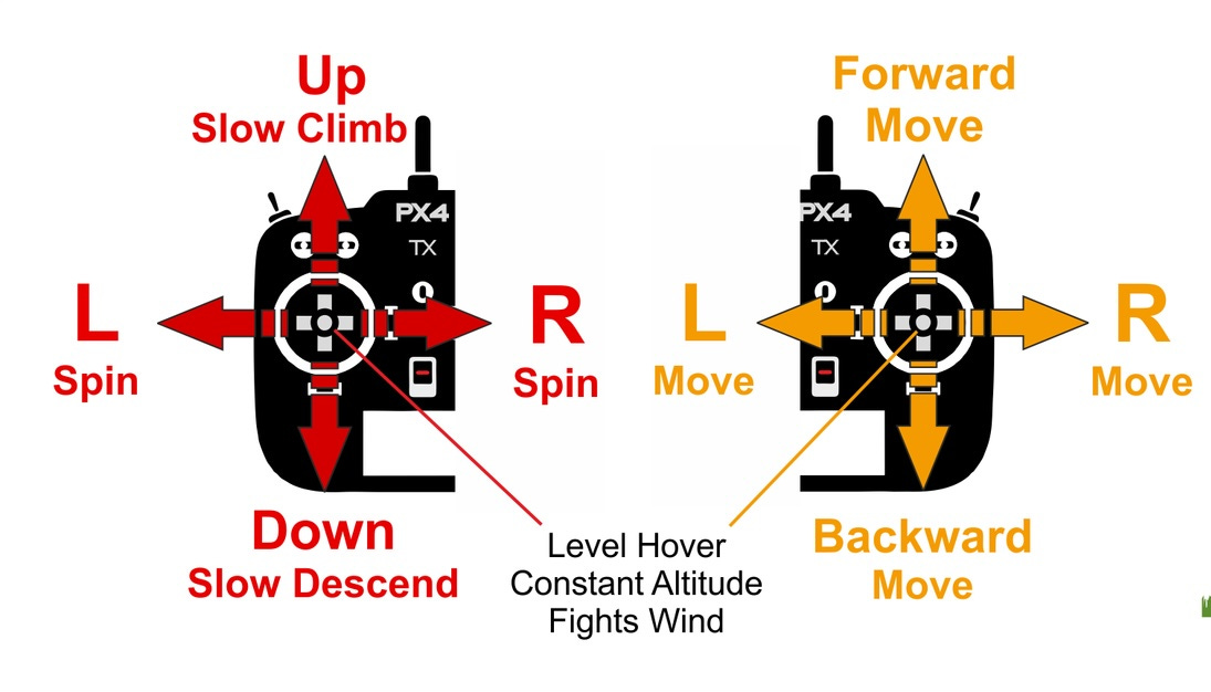
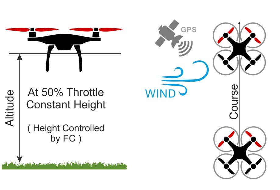
Position mode in PX4 and Ardupilot are the easiest way to learn to fly an autopilot drone. It uses GPS to counter wind drift, and allows someone with no training to intuitively grasp the controls.
I also started with Position mode because I want to build flying EVs. One of the key requirements is that it should be extremely easy to fly — as easy as using an iPhone and an order of magnitude less to think about then when driving. Position flight mode most closely mimics how I think hover should work in a flying EV operated by the pilot.
I also tested manual flight mode briefly, but crashed pretty hard. In manual flight mode, the flight controller does not counteract wind nor try to maintain altitude. It is similar to how FPV racers fly, and requires practice! I tried in a parking lot with many trees. Bad idea. I was lucky to have only broken one prop!
That just reinforced for me that flights should offload as much of the cognitive load of flying from the pilot to the system. To test that, I wanted to test what the quad could do with autonomy. After all, PX4 and Ardupilot are called autopilot systems!
GPS navigation and landing
First I tested return to home functionality. This allows GPS to fly the vehicle back to the takeoff GPS coordinates autonomously. After a basic test to ensure it was working, I wanted to see how accurate the landing could be, using GPS alone.
Armed with a yellow spatula, I did four landings using autonomous return. The accuracy was impressive, ranging from approximately 0.3-1.5 meters or 1 to 5 feet. Significantly more accurate than a smartphone would be because of their multi-constellation support and better antennas.

There are far more accurate ways to precision land a quadcopter, like using an IR-LOCK sensor, RTK positioning, and more. But for my testing, the standalone GPS was good enough.
I also tested autonomous flight missions by setting up waypoints in QGroundControl. It’s super easy to set up missions using the map based UI. You can even use it to do structure scanning and other types of preset mission patterns. I was seriously impressed with the functionality of these free and open source tools.

Obstacle avoidance — lidar
The most fascinating autopilot quadcopter capability is autonomy. Miniaturization, in part driven by smartphones, have improved performance and lowered the cost of cameras, LIDAR and other sensors that enable autonomous drones and robots.
My goal was to gain a base technical understanding of the abilities and limitations of these sensors.
$15 obstacle avoidance sensor
I started with time of flight (ToF) LIDAR sensors, because they were the cheapest and easiest way to get started in a tiny form factor. ToF sensors emit a point light source to an object, and the time of flight is measured when it bounces back. Unlike LIDAR, they reflect light off a more limited field of view, and are not used for simultaneous localization and mapping (SLAM).
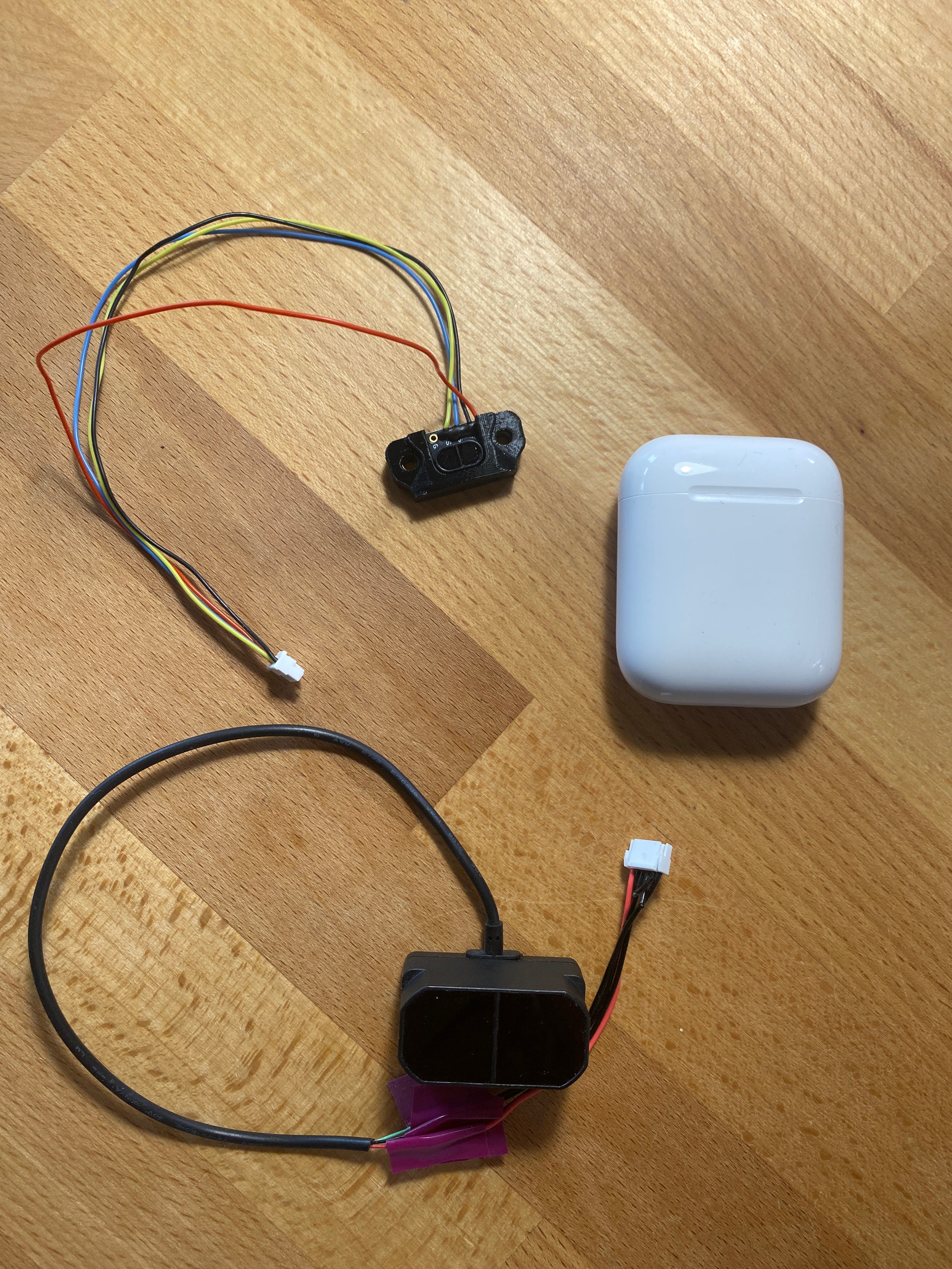
For only $15 (!), I purchased the memorably named Holybro VL53L1X ToF sensor that was practically plug and play, no soldering or even wire stripping needed. This particular sensor only has 4 meters/13 feet of range at 50 Hz sampling rate. I figured that was enough for initial testing.
I immediately ran into issues with this Holybro unit. It outputted extremely variable distance readings, like when sitting on the ground pointed at a fence about 2.5 meters / 8 feet away. The readings are on the Y axis in centimeters, time is on the X axis, as seen in this screenshot.
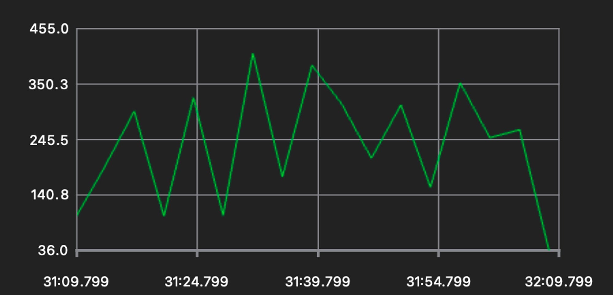
After some troubleshooting (many, many such cases), I realized the sensor has issues in direct sunlight. See how stable the following readings are, once I pointed the sensor inside, around the ~03:05:00 mark.

Clearly the $15 sensor had its limits, which were not clearly stated in the PX4 or Ardupilot docs, nor on Holybro’s product page. Oh well, on to the next one.
Next, I tried the Benewake TFmini Plus, which offers 12 meters of range and up to 1000 Hz sampling rate! The wire connector was not compatible with my Pixhawk flight controller, so I finally had to do some wire stripping and very hacky splicing.
I had more issues with this sensor. The sampling frequency was less than 1Hz, and I decided to switch to Ardupilot software from PX4 to see if that would fix the issue.
Ardupilot had better support for vision based obstacle avoidance and so this was worth the fairly small time investment. Its recommended ground control software, Mission Planner, runs natively on Windows with no Mac support and VMs were not great either. So I set up a 10 year old Surface with Windows 10 to run it, fortunately without hiccups.
Upgrading to 100 meter sensing range
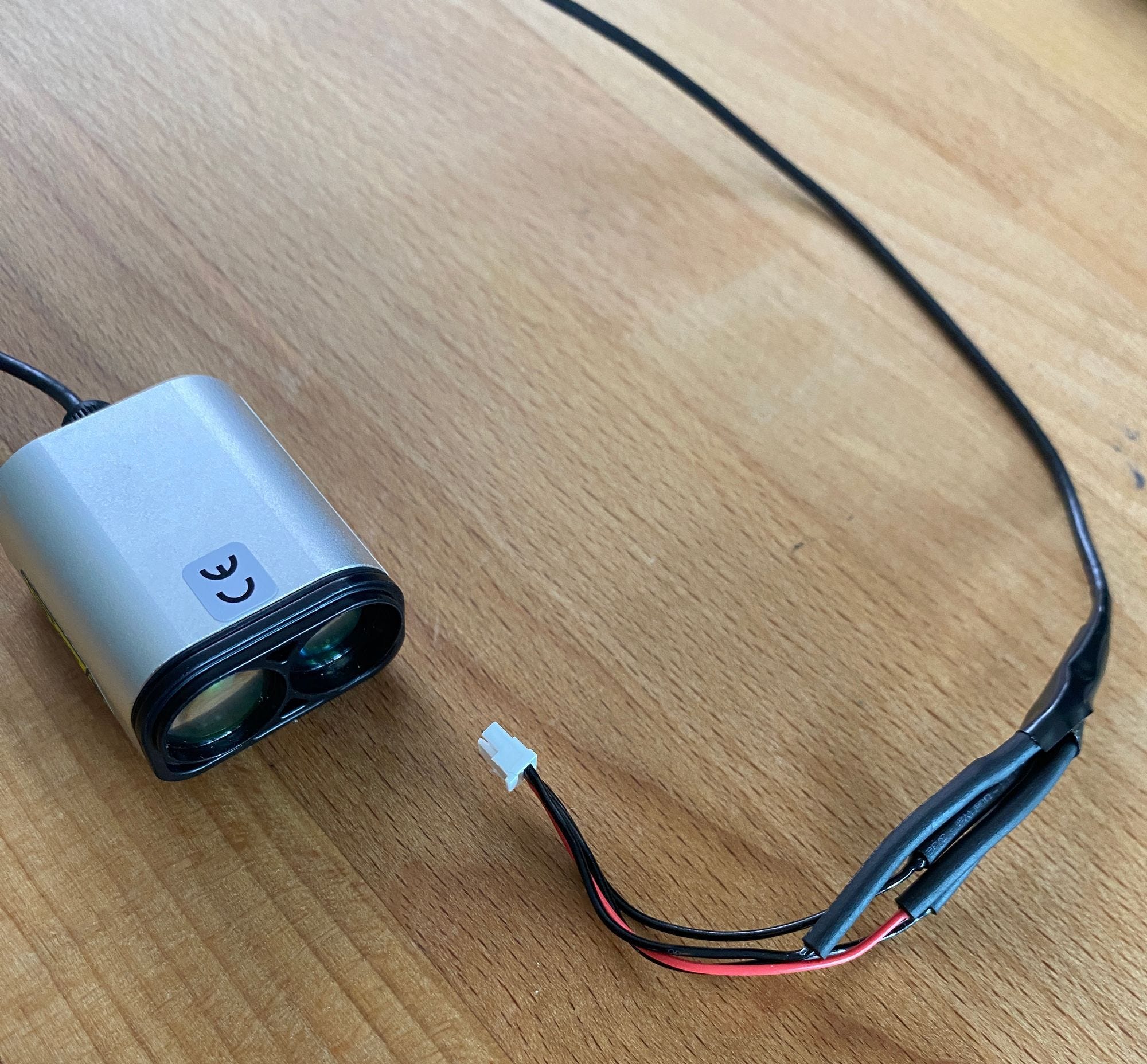
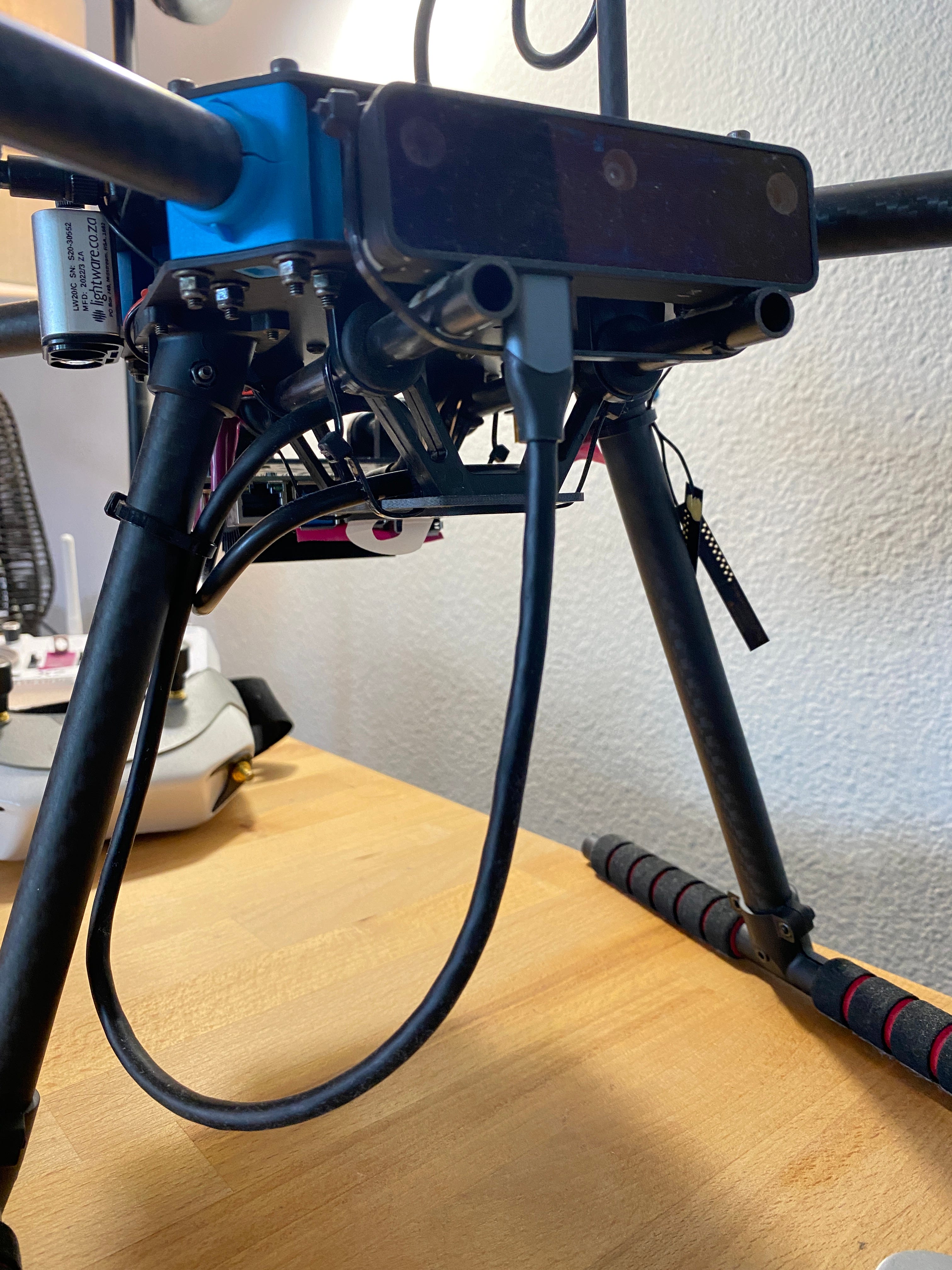
I could not get the TFmini Plus working at a usable frequency, so I switched to another ToF sensor. This time I bit the bullet and bought a high end ToF sensor for consumer drones — the Lightware LW20.
The LW20 is a huge step up from the ToF sensors I had tried. It has 100 meter range and can be configured to see through transparent materials. It is also a lot more expensive at $280. Surprisingly, it is actually engineered in South Africa, which, fun fact, is where a YouTuber currently holds the world record fastest drone hitting over 500 km/h (312 mph) without a wing.
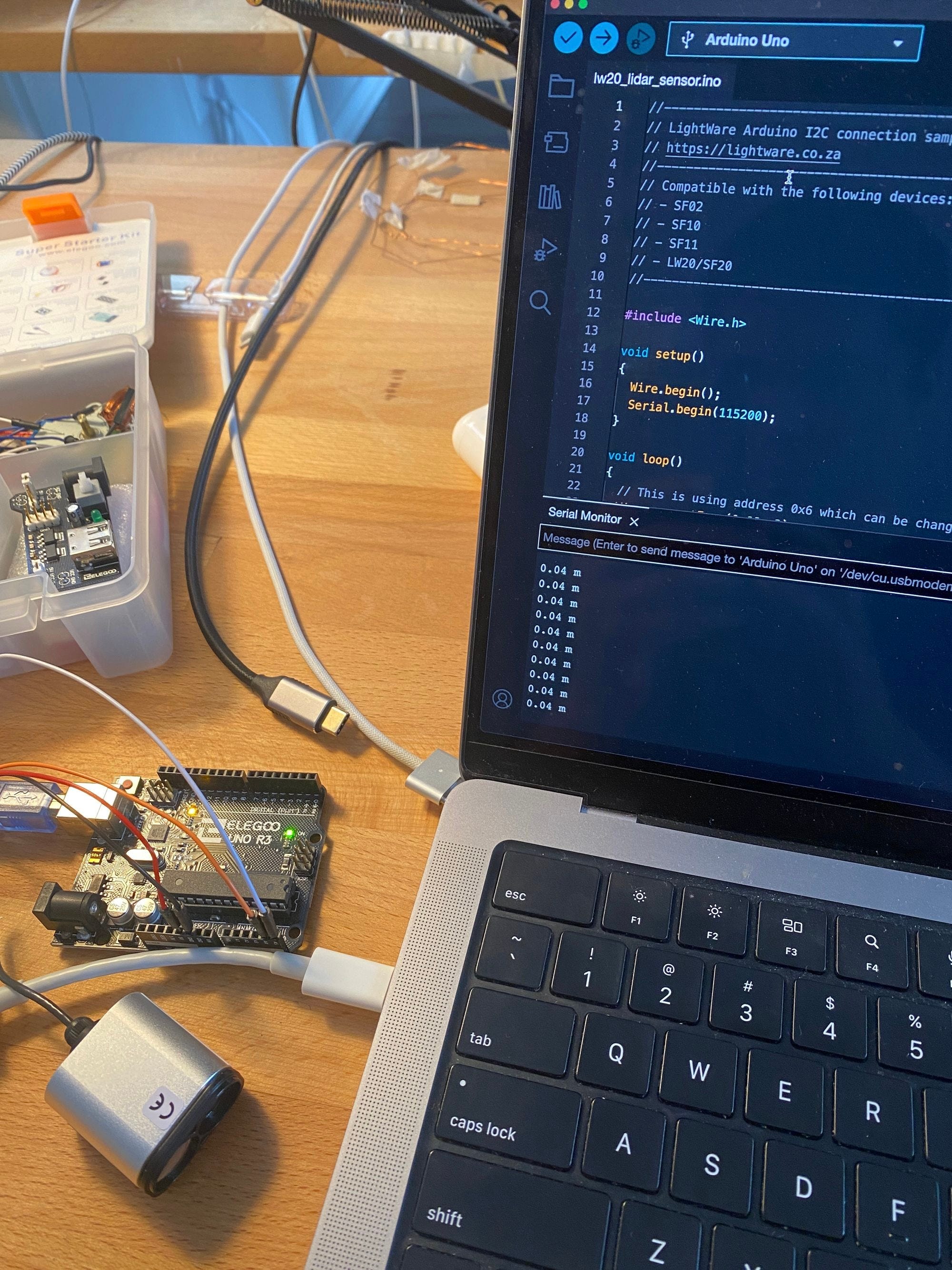
After bench testing with a Arduino-based Uno R3 microcontroller, I soldered the wiring and applied heat-shrink tubing to allow the sensor to connect to my flight controller. I had never soldered before so I was a little nervous, but it worked out fine if a bit messy. Testing at home, I was getting readings of up to 30 meters. I configured Ardupilot with a new rangefinder (distance sensor) and was ready for obstacle avoidance testing.

Field testing
The first test was simple obstacle avoidance. That is, will the quadcopter stop moving when something is in its path, even if I am directing the quad towards it?
It worked well enough! Pitching forward (right thumb) moves the quadcopter forward only as far as the sensor’s set distance. The flight controller was clearly taking the ToF sensor’s distance input, and adjusting ESC outputs to the motors.
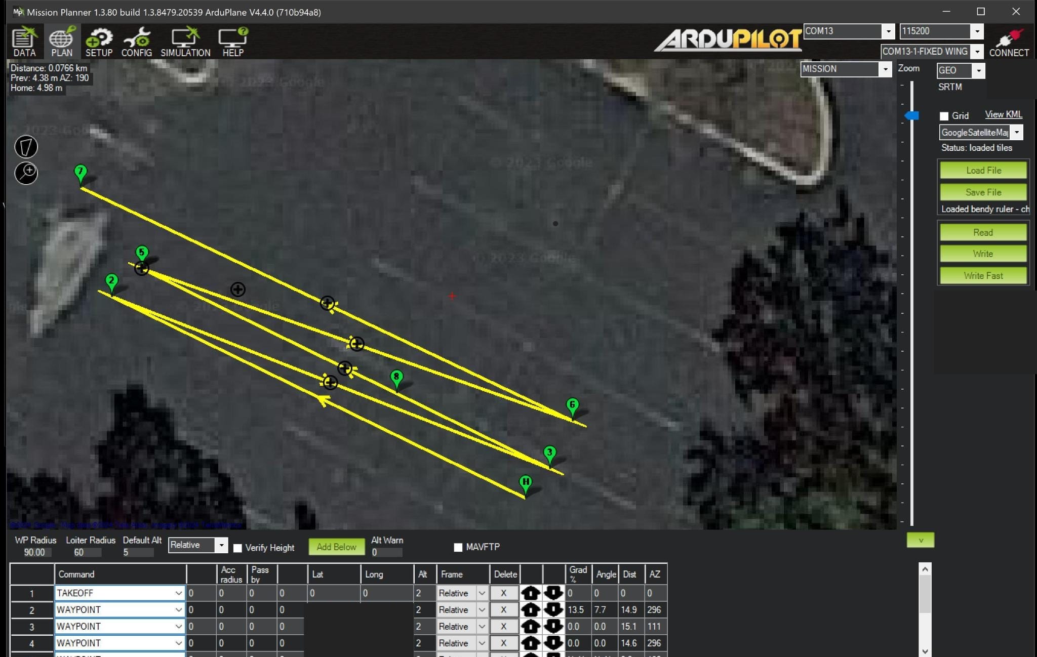
Next, I wanted to test if the quad could route around an obstacle while navigating on autopilot, using an algorithm called Bendy Ruler. Basically, the functionality allows a “lookahead” distance for the rangefinder to scan head to find obstacles. It also has a “max margin” distance which is how far away it should stay away from obstacles. Ardupilot offers vertical or horizontal avoidance strategies, which are configurable in Mission Planner ground control software.
To test if Bendy Ruler obstacle avoidance worked, I configured a simple autopilot flight plan in Mission Planner for the quad to move back and forth between two waypoints about 10 meters / 30 feet apart and at an altitude of about 2 meters / over 6 feet. It was ready for flight testing.
Bendy ruler vertical demo with the LW20 sensor:
Bendy ruler horizontal demo with LW20:
As these video demos show, Bendy Ruler was working pretty well. Sometimes the sensor did not detect the obstacle, but after some configuration, I was quite impressed overall with both the sensor and the Ardupilot software to make this possible.
Surface tracking and terrain following
The next feature I wanted to test was surface tracking / terrain following. They do exactly what they sound like, with terrain following for autopilot flight modes and surface tracking being a feature for auto and some manual flight modes.
First I tried keeping my LW20 as a forward facing rangefinder and pointing the TF Mini downward to track altitude for surface tracking. That did not work. The readings from the TF Mini were too inconsistent. It seems it is best used indoors in consistent lighting conditions. So I removed the TF mini and repositioned the LW20 to be downward facing.
Again, the LW20 performed well! Both for surface tracking and terrain following.
In this surface tracking test, you can see the quad adjusts altitude dynamically using measurements from LW20 ToF lidar.
Terrain following is a similar feature but for autonomous GPS based mission plans.
I had some minor drone hover stability issues, but not enough to derail the tests.
Obstacle avoidance — vision
The final obstacle avoidance tests I wanted to do were vision based using AI.
I had all but just over 100 hours of quadcopter tinkering experience at this point, and this was going to be a level up in difficulty.
Deciding on the hardware to do this was the first step. I would need both a camera system and a companion computer to process the images in real time. Autopilot flight controllers do not have enough compute capacity to do this, topping out not much more than 1B operations per second. Onboard companion computer with at least 2 more magnitudes of compute was needed.
Oak-D depth cameras
I looked at a couple of options for the camera system first. Luxonis’s OAK-D product range in particular had some interesting features, the most important being stereoscopic vision.
Stereoscopic vision means perceiving depth using a two camera system like our eyes. It allows for less compute intensive obstacle avoidance, at least up to the range of the system — up to 8 meters in this case. A single camera has to estimate depth using various algorithms, which meant more potential work for me in writing up scripts for image processing. The OAK-D Lite that I decided on also had longer range than competing products like Intel’s Realsense cameras, while being lighter and cheaper.
Another important benefit was that these cameras had good docs. This would be important later when prompting GPT to help with writing my custom image processing script.
There were more benefits to OAK-D’s camera systems. They were not only camera sensors, but included enough compute onboard for very light depth AI processing. In addition, Luxonis is based in the US. Also fun fact: OAK-D cameras are also used in many other robotics applications, even Figure AI used them during development.

Nvidia Jetson Nano companion computer
The OAK-D Lite camera has 4 trillion OPs of compute, which meant I could run various deep learning vision models at 15 to 30 fps at up to 640x640px. Why did I need a companion computer?
Basically
(1) for recording video output from the camera system for troubleshooting,
(2) gain intuition about how a flight/companion computer interfaces with the flight controller and sensor stack for aerial autonomy and
(3) offloading some compute from the OAK-D
So despite the extra cost ($155 at the time, a little less now), 20-30% increased weight and power draw, I bought the Jetson Nano dev kit. Though it has less compute power than the OAK-D Lite, the Jetson Nano actually outperforms it on ResNet-50 @224x224 (36 fps vs 26.5 fps), the one deep learning model I could find benchmarked by both. The exact compute capability did not matter though, as long as the Nano could do (1), (2) and (3) for me, which it was perfectly capable of.
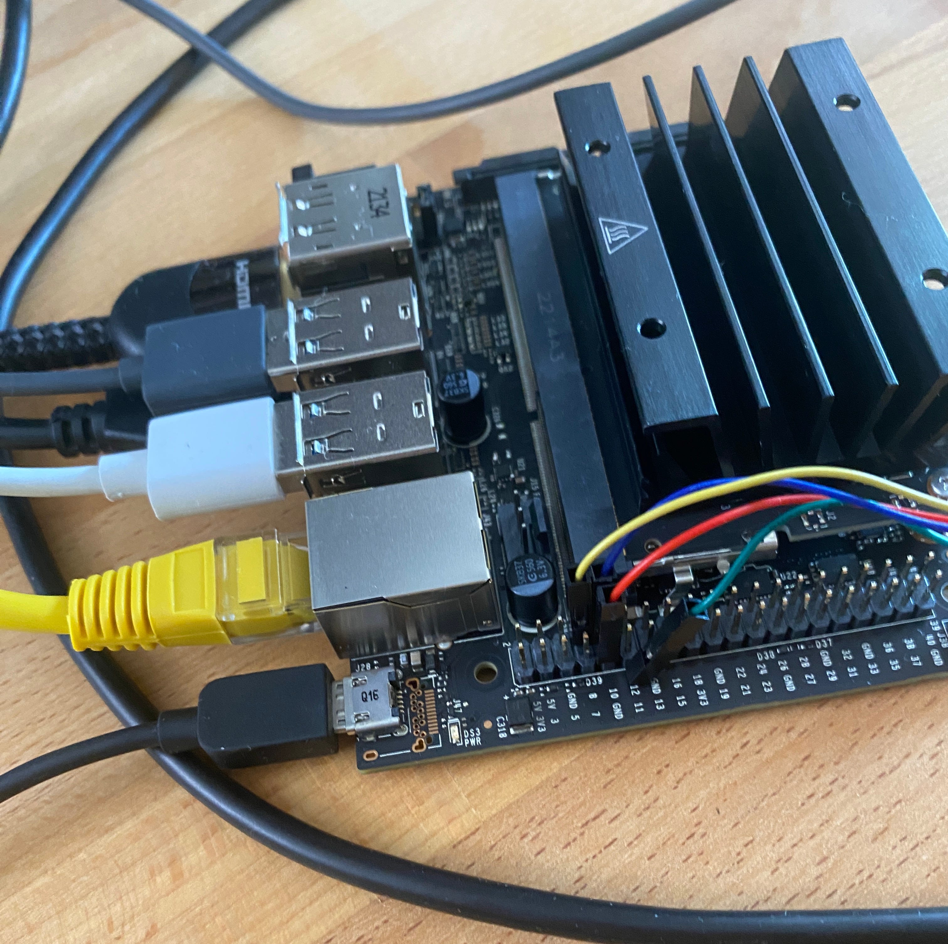
With the Jetson Nano in hand, I had to connect the OAK-D to the Nano and the Nano to the flight controller, with the help of this video and guide. I also had to make sure I could write code and push it to the Jetson Nano. I had to work out how to SSH into my Jetson Nano’s linux system from my Mac and resolve a few other software issues, which (last year’s) GPT 4 model was very helpful in doing.
I also had some space constraints mounting the Jetson Nano onto my quad’s frame. The frame has a dedicated payload platform, but it seemed more intended for a smaller (and far less powerful) companion computer like the Raspberry Pi 4. The Nano was borderline too big, given I had to connect its USB port to the USB C output from the OAK-D. That USB connection causes EMI (electromagnetic interference) issues with the quad’s GPS module in particular. I had to go through several iterations of relocating the GPS module, until I landed on putting it next to the flight controller, which was not ideal, but it worked well enough.

Power delivery was a problem too. The OAK-D Lite uses up to 5W when running image processing models and it draws power from the Jetson Nano via the USB to USB C port. However, the Jetson Nano itself draws up to 10W at 5V and 2A, which is too much to supply from any ports on my Pixhawk 6C flight controller. The Jetson Nano needed power from the PDB, power distribution board, which itself draws power from the 4S LiPo battery. I sourced a UBEC, universal battery eliminator circuit, which is basically a DC/DC converter to step-down the LiPo’s voltage to 5V. I soldered it to the PDB wiring on one end, and a DC barrel jack wire to the Jetson Nano on the other.

Python script and flight test
Luxonis has great documentation and code samples for how to use their OAK-D depth cameras. I first adapted their spatial location script to get depth distance data. My workflow was to code the script on VS Code on my Mac, and SSH the changes to my Jetson Nano. At runtime during flight testing, I would execute the Python just before takeoff. Hacky, but it worked well enough.
I moved on to Luxonis’s multi region of interest (ROI) spatial calculator. This allowed depth tracking of a wider field of view than a small bounded point source. I heavily adapted the script to display a 3x3 ROI for the whole image and show a bounding box for the ROI in which the closest obstacle theoretically is located.
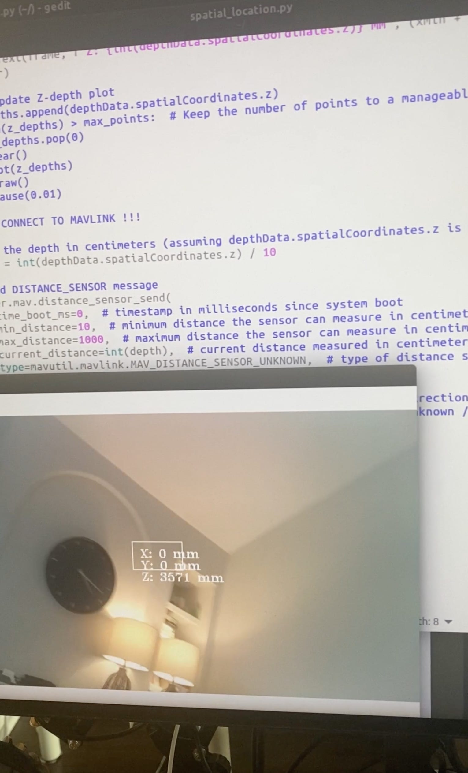
The script I got working is shown in this RGB video from the OAK-D taken during a test flight, for which I had set a 3 meter obstacle avoidance distance limit.
OAK-D Lite and Jetson Nano depth camera processing. Note the 3x3 ROIs and the detection of the nearest obstacle from these ROIs, displayed in the top left corner in realtime. At 20 seconds I am pitching the quadcopter forward, but it refuses to move because of the 3 meter distance limit from obstacles.
There was quite a bit of LLM wrangling to get the pipeline working well enough for testing. I wrote only a handful of the 200+ lines of code myself in the script. Instead I prompted GPT4 for code snippets that I could copy pasta into the script. This was mid 2023, soon after GPT4’s release, and it was already good enough to produce useable functioning code to tie together the functionality I needed. I did, however, need to ask the Arudpilot forums to resolve one problem with the script. Even with that said, it’s wild to think how much more effort this would have taken without LLMs. And this long before canvas or Claude 3.5 Sonnet.
Here is the high level breakdown of the script, summarized recently by Sonnet. I’m happy to share the full script if interested.
## OAK-D Lite:
1. Stereo depth processing
2. Spatial detection network (MobileNet)
3. Spatial location calculations
4. Color camera operations
## Jetson Nano:
1. Main script execution
2. OpenCV operations (visualization)
3. MAVLink communication
4. Video writing
The OAK-D SoC handles the depth processing, the deep learning model execution to process the depth and spatial data, and the color image data from the RGB camera for writing to an mp4 file on the Jetson Nano. The Jetson Nano visualizes the bounding boxes and displays the depth data on the video output, records the video, and sends the depth data to the flight controller using MAVLink, a simple protocol for communicating with small drones.
What's next
I was really surprised how far I was able to push obstacle avoidance with my quadcopter build. I started with no quadcopter experience or really any hardware experience.
In somewhere around 200 hours of effort, I was able to:
Learn a ton about how to assemble a modern quadcopter
Troubleshoot hundreds of hardware, software and vision script fixes
Integrate the hardware and software for lidar sensors and stereoscopic cameras
Write a working python script for detecting the nearest obstacle from depth sensing cameras
Run dozens of flight tests
While recovering from long COVID
And having a blast!
This project definitely kindled a passion for hardware and aerial mobility.
I’ve since rebuilt a radio controlled tilt-rotor VTOL after destroying the flight controller in a crash. I’m also building a 4ft/1.2m lift and cruise VTOL that is a first subscale prototype of a flying EV design I am working on.
Much more to come!
My python code script for depth obstacle avoidance is now on Github:
https://github.com/tsungxu/copter-multi-roi-depth
Thanks for writing this Xu. It has been very educational.